
The rapidly evolving construction market presents several challenges to the design and installation of a properly function- ing electrical distribution system. Supply chain issues and changes to the manufacturer’s equipment may result in unexpected delays. Electrical codes and their interpretations seem to be ever changing. Unexpected circumstances surrounding the current COVID-19 pandemic add additional constraints and concerns. Therefore, proper front-end engineering design and comprehensive power systems studies are critical to project success and must never be compromised.
Reliable power systems studies are typically provided by qualified third- party engineering companies. These studies provide critical checks and balances to ensure systems operate reliably, efficiently, and safely.
Short-Circuit Studies
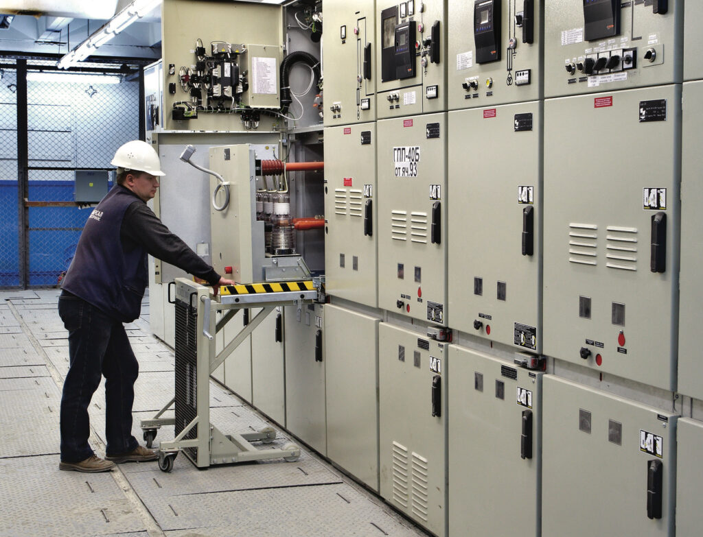
The purpose of a short-circuit study is to calculate the amount of fault current that may exist at each critical equipment location within a distribution system (Photo 1). The end goal of a short-circuit study is to evaluate the ratings of each piece of distribution equipment to ensure the equipment is installed safely. Calculations are typically performed as outlined in the IEEE Red Book (other- wise known as IEEE STD 141-1993).
Due to the complexity of the calculations involved, computer software is commonly used (and even specified by engineers) to obtain accurate results. Models built within this soft- ware will include:
- All sources of fault current within a distribution system, such as the fault current provided by the electric utility, local generators, and rotating machines.
- A system impedance model ac- counting for all cables, transformers, and reactors.
By simulating different types of faults at each key equipment location, it is then possible to see how fault currents will flow through each individual distribution system.
Fault currents at each equipment location are subsequently compared against the ratings of the equipment that is being supplied. Any equipment location found to be subjected to higher fault currents than it is rated for must be increased in rating to avoid the potential for equipment failure. In some instances, short-circuit studies may also prove that less-costly equipment with lower ratings may be adequate for an installation. The authors of this article caution that prior to making any decisions around equipment substitutions, the engineer of record must be comfortable that the study scenarios accurately represent the true worst-case scenario for both present and future conditions of the installation.
A final benefit of a short-circuit study is it can check to ensure series-rated equipment is applied with upstream pro- tective devices required to achieve the published short-circuit ratings. This is particularly relevant because this aspect is often overlooked with applications involving automatic-transfer switches — where the switches and upstream distribution equipment are specified separately and not as one package.
Coordination Studies
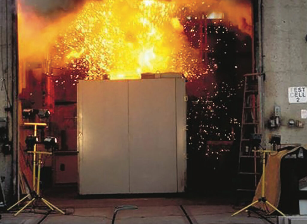
The purpose of a coordination study is to demonstrate the level of selectivity achieved in a distribution system should an abnormal condition (such as a fault or overload) occur (Photo 2). The end goals of coordination studies are to optimize adjustable overcurrent settings to protect distribution equipment, ensure outages are minimized during faults or overloads, and minimize incident- energy levels where possible throughout a distribution system.
Like short-circuit studies, coordination studies are often performed using computer software. In fact, they are often performed using the same work- ing model as the short-circuit study.
Time-current curves are created showing the tripping characteristics of cascading levels of protective devices — with current shown on the x-axis of the curve and time shown on the y-axis. For any protective device at any fault current, the device will trip somewhere between the minimum tripping time shown on the curve and maximum clearing time.
To obtain the best possible system performance, the curves are adjusted (where possible) so they do not over- lap with one another while protecting downstream system components. For circuit breaker applications, it may not be possible to obtain full selectivity across all possible fault currents — this is generally acceptable within normal distribution systems.
Emergency distribution systems or circuit branches containing other critical loads may require improved levels of coordination. If the required level of co- ordination cannot be achieved with the “as-proposed” protective devices, a study engineer can offer recommendations to improve the coordination.
In many jurisdictions, legally required, life-safety, critical, and elevator circuits are required to be “selectively coordinated” per the National Electrical Code (NEC). Interpretations of this requirement vary; therefore, it is ultimately the responsibility of the engineer of record to design and specify devices required to achieve the desired level of selectivity. At this critical juncture in the project, a coordination study engineer can be an important ally to help the design engineer analyze the characteristics of devices and offer suggestions on achieving selective coordination where it is possible within the constraints of the design.
Load Flow Studies
Unlike a short-circuit study, which reveals results during abnormal circuit conditions, a load-flow study shows system performance during normal operating conditions. The end goals of a load flow study are:
- Proving that the loading within the system will not cause voltages in the system to sag or swell to the point where system performance is impacted, or equipment may be damaged.
- Ensuring distribution equipment, transformers, and cables are not subjected to continuous currents above their rated values.
To perform a load-flow study, a system model is created that is like the short-circuit model discussed above, including fault-current contributions and system impedances. However, the load- flow model will also include the loading on each panel as specified by the design engineer on the panel schedules, along with the power factor of the loads.
For each source, continuous cur- rents and power draws are calculated along with the steady-state voltages at each key equipment location. If voltage levels are found to be outside the limits of IEEE recommended values — or if a component is found to be over-duty from a continuous current standpoint — a study engineer can help to offer solutions to the engineer of record.
These solutions may include adjust- ing transformer taps, changing the size of transformers or cables, or adjusting loads so they are fed from an alternate circuit branch.
For new construction projects, load- flow studies are specified less frequently than short-circuit, coordination, and arc-flash studies. However, it is recommended that they be performed to mitigate potential issues during energization and minimize the likelihood of troubleshooting and rework for the installation contractor.
Arc Flash Studies
An arc flash study is a safety study for personnel that is required by NFPA 70E, Standard for Electrical Safety in the Workplace, and OSHA 1910.132. A fault caused by a worker or by external factors can lead to an arc flash, which can result in a worker being exposed to dangerous levels of heat, pressure, sound, and light. The end goal of an arc flash study is to quantify the incident energy level at each equipment location so that workers can best make decisions on how to safely interact with the equipment.
An arc flash study builds upon short-circuit and coordination studies and uses many of the same data points. Knowing the available bolted fault cur- rents at equipment locations (and how long those fault currents may last) makes it possible to determine how much incident energy someone may be ex- posed to during an arc flash event. This is determined using procedures outlined in IEEE 1584-2018 – Guide for Performing Arc-Flash Hazard Calculations.
Ideally, before performing electrical work or maintenance, a circuit would be de-energized, thereby minimizing the possibility of an arc flash event or electrocution. However, it is not always possible to take these outages. If electrical work is to be performed while the equipment is energized, the owner is required to inform personnel of the electrical hazard they are subjected to, which is when an arc flash study is particularly relevant. By understanding the potential arc flash hazard and perform- ing a separate risk assessment, personnel can make the best decision on how to perform work on energized equipment.
If electrical work will be performed live, personal protective equipment (PPE) will need to be worn. PPE requirements increase along with incident energy levels, making the work on equipment more cumbersome. At incident energy levels over 40 calories/cm2, no safe PPE exists to protect a worker from the pressure wave associated with the arc flash hazard.
At each equipment location, an arc flash study will provide the available incident energy along with the working distance at which the incident energy was calculated. For most low-voltage locations, the working distance is 18 in., which is the distance the core of a worker’s body is expected to be from the arcing terminals. An arc flash boundary will also be provided, which is the distance an unprotected worker must be from the arcing terminals to be exposed to a maximum of 1.2 calories/cm2. This value is defined as the energy capable of causing a second-degree burn and establishes minimum distance requirements for workers.
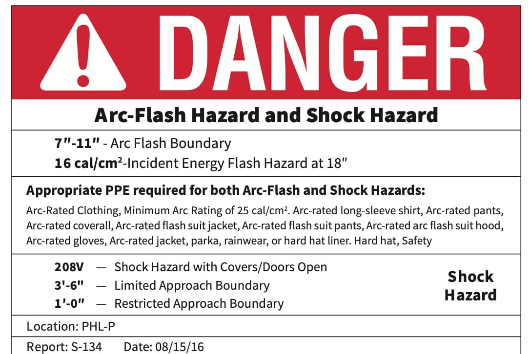
Arc flash labels, which are created after an arc flash study is complete, pro- vide the details workers require at each equipment location (Photo 3). Labels applied locally at key equipment locations inform a worker of the existing hazard at the location. The information on the arc flash labels will match the results provided in the report and will also include information for the shock hazard associated with the equipment.
Should arc flash levels be of concern to an end-user, an arc flash study engineer can also provide suggestions for arc flash mitigation to the engineer of record and building owner. As with most things, there are often tradeoffs to reducing the incident energy. Typically, that tradeoff is that more robust and costly equipment may need to be installed upstream.
Construction and the Importance of Power Systems Studies
Engineering studies are critical audits that optimize the performance of as- built electrical distribution systems. These studies ensure that the distribution equipment is applied correctly and simultaneously safeguard equipment and personnel.
The authors have been involved in numerous studies that have noted deficiencies in the initial system setup. Proper front-end engineering design and comprehensive power systems studies allow for problem mitigation before equipment is ordered, or work is performed by the installation contractor. Without per- forming these studies, such issues may go unresolved or require rework on the back end of installations, which typically delays project completion and incurs additional costs.
