Arc Flash Header
Arc Flash Boundary
Working Distance
Personal Protective Equipment (PPE)
Nominal System Voltage
Location and/or Device
Arc Flash Study Report #
Date
Service Company

Service Availability
Customer Service
Arc flash labels are designed to keep people safe. NFPA-70E was developed at OSHA’s request and sets the standards for electrical safety in the workplace. Arc flash labelling requirements are defined by the newly updated NFPA 70E 2021 standard. The goal of this regulation is to protect personnel by reducing exposure to major electrical hazards. The regulation helps companies and employees avoid workplace injuries and fatalities.
The information on an arc flash label (sometimes referred to as an arc flash sticker) is based directly on the results of the arc flash study. Arc flash studies are a requirement of NFPA 70E, while arc flash labeling requirements are specifically defined in section 130.5(H) of the regulation.
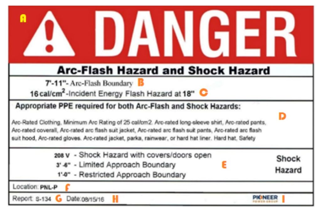
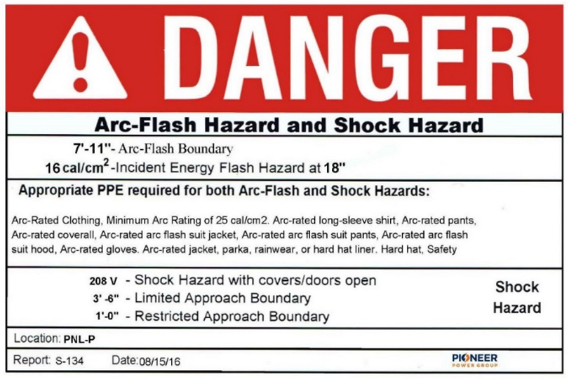
The NFPA 70E regulation states that workplace electrical equipment that is likely to be serviced should be marked with a cautionary label. The label shown here is marked with letters A – I each of which highlights an important component of the arc flash label. Each of these components is discussed in further detail below to help you understand each component of the warning label.
A – Arc Flash Header
Arc flash labels must use an ANSI Z535 compliant header with the word ‘DANGER’ in white letters on a red band or the word ‘WARNING’ in black letters on an orange band. The regulation does not provide guidance on distinguishing between the use of ‘Danger’ or ‘Warning’ on the header, however it is common to have ‘Warning’ labels applied in lower risk scenarios (i.e.: <40cal/ cm²) and ‘Danger’ labels applied in higher risk scenarios warranting a higher level of caution (i.e.: >40cal/ cm²). Ultimately this distinction is made on a site-by-site basis as requested by site personnel but should be consistent across the site.
B – Arc Flash Boundary
The arc flash boundary identifies the distance from the equipment at which an unprotected person would receive second-degree burns in the event of an arc flash. The energy at this boundary line would be equivalent to 1.2cal/ cm² or 5 Joules of heat energy. Any employee within this boundary must be wearing appropriately arc-rated PPE.
C – Working Distance
IEEE 1584 defines the working distance as “the dimension between the possible arc point and the head and body of the worker positioned in place to perform the assigned task.” The working distance is based on a calculation of the level of incident energy (cal/ cm²) at a workers’ head and torso from the potential arc source. Typical work distances range from 18-36 inches but can vary. Accepted work distances are primarily based on equipment type and are published in the IEEE 1584.
Incident energy increases dramatically as working distance decreases. When it comes to arc flash – working distance can mean the difference between life and death. If a person is located closer than the established working distance, the worker could be at extreme risk.
D – Personal Protective Equipment (PPE)
The level of PPE required at a given location is based directly on the calculated incident energy (the amount of thermal energy at a distance from an electrical arc event). This section of the label provides information about the PPE needed to safely work on the equipment. PPE requirements can be expressed in one of four methods on an arc flash label:
E – Nominal System Voltage
This section of the label provides voltage information which can be used to quickly assess the potential shock hazard of the system. Although not specifically required by the NFPA 70E regulation, most arc flash labels include shock hazard boundary information. Shock hazard boundary details include the ‘Limited Approach Boundary’ and the ‘Restricted Approach Boundary’ both of which should only be crossed by qualified workers. The restricted approach boundary is closer to the equipment than the limited approach boundary, and thus warrants further care.
Nominal system voltage is recorded in Volts and can be displayed as V, VAC or VDC (VAC = volts alternating current, VDC = volts direct current).
F – Location and/or Device
Each label is marked with the specific location and device which the label applies to.
G – Arc Flash Study Report #
Since the information on the arc flash label is based directly on the results of the arc flash study, the study reference number is marked on each label so that the study can be referenced at any time if necessary.
H – Date
Since NFPA 70E requires that a study be completed every time there is a change in equipment, or every five years at minimum, all arc flash labels should include a study date. This date corresponds to the date of the arc flash risk analysis.
I – Service Company
Indicates the name of the company which has provided the arc flash analysis services.
Arc Flash Header
Arc Flash Boundary
Working Distance
Personal Protective Equipment (PPE)
Nominal System Voltage
Location and/or Device
Arc Flash Study Report #
Date
Service Company

Electrical safety is a top priority in any industrial setting. Compliance with regulatory standards is not only mandatory but also essential for safeguarding your workforce
In the ever-evolving landscape of industrial safety, it is crucial for companies to stay ahead of the curve and adopt the latest industry practices. One
In the ever-evolving world of electrical safety, staying up to date with the latest standards and regulations is crucial for businesses. Arc flash incidents are a significant concern in various industries, posing serious risks to personnel and equipment. To mitigate these risks, it is essential to adapt to modern electrical safety standards, and one key tool in this process is the Arc Flash Study. In this article, we will explore the importance of Arc Flash Studies and their role in ensuring a safe and compliant working environment.